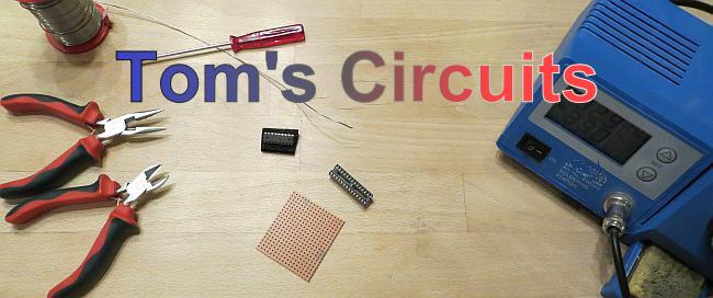
There isn't much, really. First, solder the microcontroller's socket to the perfboard, then the socket of the driver. I didn't use a socket for the driver initially, which I regretted later...
Here is a schematic.

If you do this in a clever way, there will not be too much effort in connecting the driver to the controller. Port B controls the common cathodes, so all port B pins connect to the driver inputs (green). PB0 is on the wrong side of the controller, but that is no problem. PB6 and PB7 are somewhat out of place. I simply used two wires to connect them. That won't win me a beauty contest, but the electronics will vanish under the cube anyway. Make sure that PB6 and PB7 are connected in the right order: It changes between the controller and the driver.
OK, start by positioning the two ICs/sockets. Note that there is an offset of two holes on the board.

Solder.

Now, connect port B to the driver. Start with the conveniently placed ports 1 to 5. I didn't even use wires, but it might be easier to do so.

Now turn the board over and connect the two ground pins of both ICs.

Next, connect port 6 and port 7 using wires. Note that the yellow and white wires are changing order.

On the bottom side, connect port 0 to the driver (here marked in yellow) and connect analog and digital ground on the ATMega8 (black wire, white outlines).

Also connect digital and analog Vcc pins (red wire, pins VCC and AVCC) and GND pins.

Finally, add a red and a black wire to the ATMega's Vcc/Gnd pins do connect your battery. Done!

Final Assembly
Now we have to connect cube and electronics. For this we need another sixteen wires. Let's start with the common cathodes, i.e. the LED groups. So far that vertical wires from each group just end on the board. Now we need to connect wires to each of them.

And we connect them to the driver output. Start with the top right group, then connect the top left group. Continue with the second level. Keep alternating between right and left.

Do exactly the same thing with the bottom layers (layer 3 and 4). Alternate between right and left as shown.

Now connect the columns of the cube. Here is how. This time there is no driver; the columns of the cube are directly connected to the microcontroller. Here is a bottom view of the cube. Every column is shown with their respective controller pin.


Connect the LEDs in the right order. Start in the corner and connect all four LEDs of one row.

Then connect the LED anodes of the second row. Here, two columns are connected.

And the last two anodes are done.

If your wires aren't too long, you can flip the electronics over and hide the wiring.

I fixed the two parts of perfboard to each other with a few pieces of wire. I soldered them to one board, inserted threaded them through the other board and just bend them at 90°. See the picture below.

And that is the hardware completed. In the picture below, there is a pigtail connected to the ISP pins of the controller. I used that to program the controller while I kept adding new patterns. Depending on your means of programming, you might or might not need this.

So, all that is left is the software. A brief description and the final part of this project will be posted in part 4.


i need part 4
ReplyDeleteGreat project. I loved it.
ReplyDeleteNeed also the part 4. But you have do a very great and beautiful proyect. Thanks for demostrate it for me.
ReplyDeleteThanks! Part 4 is up. The SW is available for download.
DeleteSorry for the delay, but xmas preparations had a higher priority...
Hello , how i can add programmming cable ? In your explanations i dont see how to do that ... Help me ...
ReplyDeleteI made a schematic. Go to
Deletehttp://tomscircuits.blogspot.de/2013/04/ATMega8ISP.html
Hello,
ReplyDeleteThe ISP use the pins PB3, PB4 and PB5 but they are also used pour the leds, doesn't it cause any troubles ?
A very good question. Ideally you wouldn't use the ISP pins for dual purposes. But in this design it is too convenient in terms of layout and software to do so.
DeleteIn my design, I actually assume that the controller gets programmed elsewhere. But it really isn't a problem to use the ISP pins.
In ISP mode, the controller output (MISO) can drive both, the ISP programmer input and the LED driver input. The ISP inputs (SCK, MOSI) can be driven in parallel to the LED driver inputs. So all is fine.
thank you for your response
DeleteHi Tom,
ReplyDeleteWhat driver do you use?
Please read part 1.
DeleteHi Tom,
ReplyDeletegreat job. I'm building one myself using your Instructions but I want to try it with an MSP430 instead of the Atmel, I will keep you updated. But I will probably post some questions when I'm done soldering and wiring and need to programm it :)
Georg, interesting idea. But check the data sheet to see if your MSP430 can actually drive 8 x 20mA.
DeleteLet me know how you get on. And don't ask me any MSP questions. I have no experience with them. Although I do have a launchpad lying around somewhere... :-)
Hi Tom, thanks for the reply. No, the MSP can only drive 8 x 6mA, but i thought if i would use the right driver then it should work out. One circuit for the MSP and one circuit for the driver. I just need a driver which can provide the right current or i'll build one myself with the right transistors.
DeleteHi Georg, just wanted to make sure you are aware of that point. I am very interested in your project, so please do report your progress. Also, if you have a link to a project page, please post it here in the comments.
Delete8052 Instead ATMEGA8L ?
ReplyDelete8051/8052 Microcontroller
ReplyDeleteMay be possible, but I don't know this controller. You will definitely need to rewrite the software.
Deletehttp://www.jide-ic.cn/uploadfile/617/product/b/129223419940872500.jpg
Deleteat89s51
As I said, it might be possible, but you have to rewrite all HW related software.
DeleteI wouldn't recommend this as a beginner project.
hi tom i.am going crazy. I ordered a kit online and have no instructions. I usually use arduino but i have burnt it out. anyways I have cube built but have no clue how to do the wiring. this kit came with a sound sensor as well as two buttons. the chip is an 351-SkDip28
ReplyDelete15f204ae
I have no clue how to do this and have searched online and came up empty so Im reaching out to you.
Hope you can help
HI TOM. im using your instructions in making the project. im trying to use atmega32 for this project but the codes is in C. any idea for FLOWCODE?
ReplyDeletehope you can help.
Hi Brian, I have no experience with Flowcode, so I am afraid you are on your own.
DeleteWhy not try C? I suspect that the ATMega32 is not that different from the ATMega8 that I have used. So as long as you use the same pins, porting the code is probably not too complicated.
This comment has been removed by the author.
ReplyDelete